
Journey Sand Shader
Recreating Journey’s sand shader in Unity.
By Hans Meulblok

Table of contents
1. Introduction
The game Journey is one of my favourite games, from the visual story telling to the recognizable aesthetics. For my research subject I wanted to try recreating the sand shader they used within Unity using HLSL.
I have wanted to get into shader programming for a while now and I thought this was the perfect opportunity. For this research assignment I also wanted to learn more in-depth about procedural generation, I wanted to combine these two subjects. Then I also wanted to give aeolian erosion simulation a shot when I came across Nick McDonalds work on procedural dunes.
As excited as I was to create my “Journey-desert-generator with particle simulation”, I fell into the most common pitfall in the game development business: an unfeasible scope. luckily I didn’t realise that too late. I redefined my scope later in the development process. But at the start of my research my goal was to create a tool that procedurally generates a terrain, erodes this terrain to look like a desert and finally applies the beautiful Journey sand shader to finish it.
I decided I wanted to create my own procedural generation algorithm from scratch with maybe a little help from tutorials. My particle simulation I wanted to base on either hydraulic simulation techniques because they are similar or I wanted to try and recreate Nick Mcdonald’s his implementation. You can see an example of his algorithm at work in the twitter post below. The sand shader I wanted to create would be based of Alan Zucconi’s work on recreating the shader (Zucconi, A. 2018) and John Edwards’ GDC talk on Journey’s sand rendering (Edwards, J. 2013). I already thought out what my dunes should look like so I would have a goal to work towards. In figure 2 you can see my thought process and the approach I wanted to take.

2. Mesh Generation
I started development by creating a terrain generator a little more complex than just using Perlin Noise. I wanted to create something that I could use in the editor because I don’t like having to enter play mode in Unity every time I want to generate something slightly different or if I want to make a small change and inspect the results. Of course I first had to generate a mesh before I could go and adjust heights and all that. I use the code shown below to construct my mesh.
Vector3[] verts = new Vector3[m_MapSize * m_MapSize];
        int[] triangles = new int[(m_MapSize - 1) * (m_MapSize - 1) * 6];
        int t = 0;

        for (int y = 0; y < m_MapSize; y++) {
            for (int x = 0; x < m_MapSize; x++) {
                int i = y * m_MapSize + x;

                //assign height
                Vector2 percent = new Vector2 (x / (m_MapSize - 1f), y / (m_MapSize - 1f));
                Vector3 pos = new Vector3 (percent.x * 2 - 1, 0, percent.y * 2 - 1) * m_Scale;
                pos += Vector3.up * m_Map[i] * m_ElevationScale;
                verts[i] = pos;

                // Construct triangles
                if (x != m_MapSize - 1 && y != m_MapSize - 1) {

                    triangles[t + 0] = i + m_MapSize;
                    triangles[t + 1] = i + m_MapSize + 1;
                    triangles[t + 2] = i;

                    triangles[t + 3] = i + m_MapSize + 1;
                    triangles[t + 4] = i + 1;
                    triangles[t + 5] = i;
                    t += 6;
                }
            }
        }
Code snippet 1 method that constructs a mesh.
2.1 Terrain generation
Now that we have a flat mesh to manipulate it is time to add height to the vertices in said mesh. In a separate C# script I made a heightmap generator. I made this script based on what I learned in the procedural generation workshop and my prior knowledge on the subject. The code shown below is my final version of the heightmap generator. My initial mesh tests were generated using only the built in Perlin Noise function that Unity has. But this did not offer many interesting variations in generation because it was only one layer of noise. I improved on this by using Octaves or multiple layers of noise on top of each other. A visual representation of this can be seen in Figure 2. This resulted in more interesting landscapes. The result of this can be seen in figure 3.


var map = new float[mapSize * mapSize];

        //set seed
        m_Seed = (m_RandomizeSeed) ? Random.Range (-10000, 10000) : m_Seed;
        var prng = new System.Random (m_Seed);


        //noise layers
        Vector2[] offsets = new Vector2[m_NumOctaves];
        for (int i = 0; i < m_NumOctaves; i++) {
            offsets[i] = new Vector2 (prng.Next (-1000, 1000), prng.Next (-1000, 1000));
        }

        float minValue = float.MaxValue;
        float maxValue = float.MinValue;

        // use different layers of noise for the height
        for (int y = 0; y < mapSize; y++) {
            for (int x = 0; x < mapSize; x++) {
                float noiseValue = 0;
                float scale = m_InitialScale;
                float weight = 1;
                for (int i = 0; i < m_NumOctaves; i++) {
                    Vector2 p = offsets[i] + new Vector2 (x / (float) mapSize, y / (float) mapSize) * scale;
                    noiseValue += Mathf.PerlinNoise (p.x, p.y) * weight;
                    weight *= m_Persistence;
                    scale *= m_Lacunarity;
                }
                map[y * mapSize + x] = noiseValue;
                minValue = Mathf.Min (noiseValue, minValue);
                maxValue = Mathf.Max (noiseValue, maxValue);
            }
        }
Code snippet 2 important part of the heightmap generator where noise is created and applied.
2.2 Particle erosion
Nick Mcdonald’s implementation of particle erosion to create a desert is really impressive, naturally I wanted to create a particle erosion system just like the one he made (Mcdonald, N. 2020). He based it off of his own hydraulic erosion algorithm. So I figured I would do the same thing: I looked into how hydraulic erosion worked by looking at a video made by Sebastion Lague (Lague, S. 2019) and reading Nick’s blog about his work. I noticed that I found hydraulic erosion already quite challenging on its own and adding aeolian erosion / wind erosion would only make things even harder. With hydraulic erosion you only have to simulate the descent of a particle but with aeolian erosion you have to keep in mind that sand behaves different from soil or rock when eroded. Sand can cascade downhill or abrade against sloped surfaces not to mention that sand can also be lifted off the ground by a wind force. See figure 5 for a visual representation. Nick’s implementation also includes using a map that keeps track of what part of the mesh could be eroded by wind and by how much.

Because figuring out how to simulate all this would take too much time I decided to settle with what I ended up with after a week. What I did was try and create a fake aeolian erosion effect. What I used to achieve the effects shown in the images below was also based on hydraulic simulation like my sources suggested but I did not create an algorithm that also abrades and cascades: instead it just erodes the mesh in one direction (the wind direction), you can adjust this in the editor but more on that in the chapter about the editor tool I made. Particles have a lifespan, a direction, a volume for how much sediment it can move across its path and a speed. I adjusted it so particles can flow uphill or even go over: resulting in something that vaguely looks like it has been eroded by wind.

Figure 6 Uneroded mesh, 4 layers of noise. 
Figure 7 Eroded mesh, 50 000 p in 2673ms.
On the mesh shown in figure 6, 50.000 particles were simulated in 2673ms. The result is visible in figure 7. Each particle has a certain set of features and behaviours they go through. In the code snippet below the particles are dropped somewhere on the mesh and given a direction, after which the height and gradient are calculated to simulate where the particle would be flowing to based on nearby points in the mesh, just like in hydraulic erosion. But the particles don’t have that much freedom in their movement, it is just meant to give a little more variation to the movement of the particle because straight lines across the mesh wouldn’t be that interesting.
for (int lifetime = 0; lifetime < m_MaxParticleLifetime; lifetime++) {
                int nodeX = (int) posX;
                int nodeY = (int) posY;
                int particleIndex = nodeY * mapSize + nodeX;
                // Calculate particles offset inside the cell (0,0) = at NW node, (1,1) = at SE node
                float cellOffsetX = posX - nodeX;
                float cellOffsetY = posY - nodeY;

                // Calculate particles height and direction of flow with bilinear interpolation of surrounding heights
                HeightAndGradient heightAndGradient = CalculateHeightAndGradient (map, mapSize, posX, posY);

                // direction
                dirX = m_Direction * m_Inertia - heightAndGradient.gradientX;
                dirY = m_Direction * m_Inertia - heightAndGradient.gradientY;

                // Normalize direction
                float len = Mathf.Sqrt (dirX * dirX + dirY * dirY);
                if (len != 0) {
                    dirX /= len;
                    dirY /= len;
                }

                //move
                posX += dirX;
                posY += dirY;

                // Stop simulating particle if it's not moving or has flowed over edge of map
                // limit if going to a high pos
                if ((dirX == 0 && dirY == 0) || posX < 0 || posX >= mapSize - 1 || posY < 0 || posY >= mapSize - 1) {
                    break;
                }
Code snippet 3 particle movement.
The movement of the particle is now determined. The next step is to calculate how much sediment it can carry and drop at certain criteria. In the code snippet below the eroding part of our particle simulation is calculated. Either the particle has too much sediment on it and / or is going too far up hill and it will drop sediment. If it is not at maximum sediment capacity the particle is allowed to erode from nodes within the radius of the particle. The erosion brush method is used to remove height from nearby nodes and add it to the capacity of the current particle.
// Find the particle's new height and calculate the deltaHeight
float newHeight = CalculateHeightAndGradient (map, mapSize, posX, posY).height;
float deltaHeight = newHeight - heightAndGradient.height;

// Calculate the particle's sediment capacity (higher when moving fast down a slope)
float sedimentCapacity = Mathf.Max (-deltaHeight * speed * volume * m_SedimentCapacityFactor, m_MinSedimentCapacity);

// If carrying more sediment than capacity, or if going too far uphill:
if (sediment > sedimentCapacity || deltaHeight > 2) {
    // If moving too far uphill (deltaHeight > 2) try fill up to the current height, otherwise deposit a fraction of the excess sediment
    float amountToDeposit = (deltaHeight > 2) ? Mathf.Min (deltaHeight, sediment) : (sediment - sedimentCapacity) * m_DepositSpeed;
    sediment -= amountToDeposit;

    // Add the sediment to the four nodes of the current cell using bilinear interpolation
    // Deposition is not distributed over a radius (like erosion) so that it can fill small pits
    map[particleIndex] += amountToDeposit * (1 - cellOffsetX) * (1 - cellOffsetY);
    map[particleIndex + 1] += amountToDeposit * cellOffsetX * (1 - cellOffsetY);
    map[particleIndex + mapSize] += amountToDeposit * (1 - cellOffsetX) * cellOffsetY;
    map[particleIndex + mapSize + 1] += amountToDeposit * cellOffsetX * cellOffsetY;

} else {
    // Erode a fraction of the particle's current carry capacity.
    // Clamp the erosion to the change in height so that it doesn't dig a hole in the terrain behind the particle
    float amountToErode = Mathf.Min ((sedimentCapacity - sediment) * m_ErodeSpeed, -deltaHeight);

    // Use erosion brush to erode from all nodes inside the particle's erosion radius
    for (int brushPointIndex = 0; brushPointIndex < erosionBrushIndices[particleIndex].Length; brushPointIndex++) {
        int nodeIndex = erosionBrushIndices[particleIndex][brushPointIndex];
        float weighedErodeAmount = amountToErode * erosionBrushWeights[particleIndex][brushPointIndex];
        float deltaSediment = (map[nodeIndex] < weighedErodeAmount) ? map[nodeIndex] : weighedErodeAmount;
        map[nodeIndex] -= deltaSediment;
        sediment += deltaSediment;
    }
}

// Update particle's speed and  volume
speed = Mathf.Sqrt (speed * speed + deltaHeight * m_Gravity);
volume *= (1 - m_DisappearSpeed);
Code snippet 4 particle erosion
2.3 Editor tool
While adjusting values in the inspector or adjusting code because it wasn’t working like I wanted to I had to press play and wait until everything had loaded and compiled. This really became an issue once I started using the particle simulation because I ran the script as soon as I entered play mode so the loading time would be even longer.
My solution for this was making a simple editor script that lets me simulate my project outside of play mode in Unity. The two buttons you can see on the Mesh Generator script need to be used in that order and allow you to create a mesh and erode it in the editor. The only thing I have to wait for at this point is for the simulation to finish or for scripts to compile which is not nearly as long as doing everything in play mode. I found that simulating while going into play mode takes roughly two to three times as long as doing it in the editor. While loading times did vary a lot, my workflow and mood improved by having shorter waiting times.
In editor: 2099ms +/-
Going into playmode: 5000+

3. Redefining my scope
While I was working on my erosion algorithm I started to realise that my scope was too big and too broad. I wanted to create a procedural desert generator with realistic aeolian erosion while also working on replicating the Journey sand shader. This was simply too much to do in 4 weeks and they are pretty much two different projects. I realised this at the end of the second sprint, so the second week into my research. I decided that I was going to focus on recreating the sand shader for the remaining time and leaving the erosion algorithm as it is. The erosion algorithm wasn’t nearly as impressive as what I aimed for but it does look like a wind force has eroded the mesh.
4. Sand shader
I have been fascinated by the game Journey ever since I played it. While doing research for another project of mine I found this GDC (Edwards, J 2013) talk en soon after I found Alan Zucconi’s tutorial on the shader (Zucconi, A. 2018).
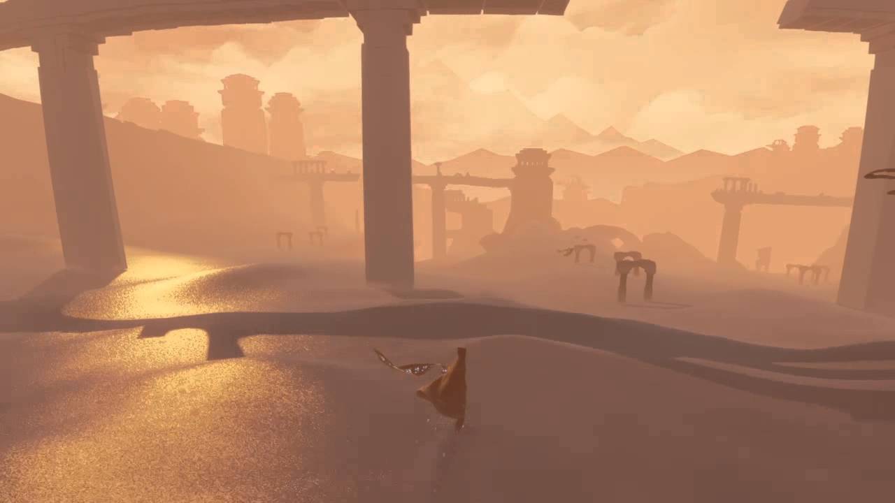
His reference was based off of one of the initial scenes of the game, a seemingly endless desert with a big mountain in the distance revealing your goal in the game. He based his work on that of someone else who also tried to replicate the Journey Aesthetics (Deng, A. 2018). I thought it would be interesting to try and replicate the golden look the sand has in this part of the game in figure 9. I really love the colours in this scene and it makes the sand look like liquid gold.

4.1 Diffuse contrast
In the GDC talk from 2013, John Edwards explained that the reflectance model they ended up using was made by themselves based on a series of trials and errors during the development process (Edwards, J. 2013). Their goal wasn’t to make it photorealistic but to give life to something that would be instantly recognisable just by the aesthetics. And that they did.
The shading model they devised follows this equation:
I = 4* ((N o [1, 0.3, 1]) . L) Where “o” is the element-wise product between two vectors, N is the surface normal, L is the light direction and “.” is the dot product. This lighting model was shown in the GDC talk and John Edwards referred to it as diffuse contrast.
Diffuse contrast is at it’s core still based on Lambertian reflectance as the lighting model for that looks like this equation below (Zucconi, A. 2016).
I = N . LOne of the big differences is that the overal result is multiplied by 4 as you can see in the first equation, which means the transition from light to dark is way smaller.
To finish the diffuse we still need to add colours. With the lighting model we can lerp between the shadow colour and the terrain colour we set in the inspector. We use the lighting model as the scalar weight for the lerp.
float NdotL = saturate(4 * dot(N * float3(1,0.3,1), L));

			// the colours
			if (_DiffuseEnabled == 0)
				NdotL = saturate(dot(N, L));

			float3 color = lerp(_ShadowColor, _TerrainColor, NdotL);
			return color;
Code snippet 5 adding diffuse to the terrain colour.
The result of this will look like this.

4.2 Sand normal
One of the effects that makes the Journey lighting so recognisable is the granularity of the sand. By looking at figure 9 from earlier in this article it looks like the sand is not smooth but built up from millions of grains of sand and that definitely is not the case. The technique that accomplishes this is called bump mapping. This allows light to reflect on a flat surface as if it would be a more complex one. With a zoomed in screenshot you can see the subtle difference when we apply a randomised texture in the figures below.

Figure 11 Mesh with diffuse colour only. 
Figure 12 Mesh with a bump map made from a sampled texture.
While in real life each grain of sand can preturs the light in a different way, replicating this realistically in a shader would be unfeasible. What we can do is “fake” this effect by altering the normal directions using a texture. We can do this in the surf function in a surface shader. This function causes the shader to draw parts of the 3D model where o.Albedo is for it’s colour, o.Alpha for the transparency. But the one we need is o.Normal which can be overwritten to alter how light will reflect on the model. So all we need to do is write a new vector to o.Normal in the surf function.
o.Normal = N // change the normalIt is important to understand that not each grain of sand will scatter the light in any direction. While it is possible and there are models that support that, the solution used in the game Journey is much simpler and effective for what they wanted to achieve.
Alan Zucconi explained it in his articles on the subject as the following:
“For each point on the model, a random unit vector is sampled from a texture. Then, the surface normal is tilted towards that vector by a certain amount. By carefully authoring the random texture and choosing an appropriate amount of blending amount, we can perturb the surface normal just enough to add a grainy feeling to it, without losing the overall curvature of the dunes.” (Zucconi, A. 2019).
The random values are sampled from a texture filled with random colours. This texture is generated from a Gaussian distribution. This was mentioned by John Edwards during his GDC talk (Edwards, J. 2013). It ensures that the predominant direction was the one aligned with the surface normal.

To implement this we need to use a texture where we sample from, in code written as _SandTex. Remember _SandStrength, this will be used after we have sampled from the texture.
_SandTex("Sand Direction (RGB)", 2D) = "white" {}
_SandStrength("Sand Strength", Range(0,1)) = 0.1
We could now sample this texture, get the uv coordinates and return this in a function and use it for the bumpmapping. But the result of this would be too grainy. The curved surfaces will blend into each other and look like figure 14.
float3 randomSample = tex2D(_SandTex, uv).rgb
float s = normalize(random * 2 -1);
return s;
Of course this is not the result we are after. We can’t have completely random normals all over our mesh. To fix this we need to blend between the mesh normals and _SandTex. What I mean by this is that we should be able to control the amount or “tilt” the normal direction by an amount.
So if we want to interpolate between two unit vectors using slerp would be a great idea. It can safely interpolate between unit vectors resulting in another unit vector which is exactly what we need. Except for the fact that slerp is really expensive to use. I don’t think I could explain this as well as this article does. What we can do instead is use lerp to interpolate between the two directions and normalise the outcome which will result in a unit vector. There is a function built in for this called NLerp With that we can also add a value to control how much we want the light to reflect with _SandStrength. With the code snippet below we can now tilt between the normal vectors between the randomised direction sampled from _SandTex.
float3 S = normalize(tex2D(_SandTex,TRANSFORM_TEX(uv,_SandTex)).rgb * 2 - 1);
float3 Ns = normalerp(N, S, _SandStrength);
The result of this will look like this in figure 15. The subtle difference is more visible in figures 11 and 12.

4.3 Specular reflection
The third part of the surface shader I made will make the desert look more like an ocean of sand.

The way the sand shines in the light is another iconic and recognisable aesthetic from Journey. A reflection like those in the sand is called specular, from the Latin speculum. Specular reflection is a term that includes all interactions in which light is reflected in one direction, instead of being scattered or the way diffuse works. Journey features 3 different types of specular lighting: rim lighting, ocean specular and glitter reflection. Glitter reflection will be covered later because it’s a little different from the other two which you will see.
Rim lighting
The dunes in Journey have a limited set of colours. While this does add to the clean and simple aesthetic Journey has, it makes it difficult to distinguish where one dune ends and another begins. To compensate for this the sand shader gives the edge of each dune a subtle shimmering effects which highlights it. This prevents the dunes from disappearing behind each other. Once we have made our RimColour function we can add this to our colour in our custom lighting function.
float3 diffuseColour    = DiffuseColour (N, L);
float3 rimColour     = RimLighting  (N, V);

float3 colour = diffuseColour + rimColour;
return float4(color * s.Albedo, 1);
To achieve the rim lighting we are after we use the most well kown lighting model for this called the Fresnel reflectance model. The Fresnal model states that the intensity of the light I is given by:
I = (1 – N . V)^power * strength
Where power and strength are two parameters to control the contrast and strength of the effect. To visualise where this applies on the mesh in figure 17 you can see a sand dune viewed by the camera (blue arrow). The red arrow stands for the surface normal on top of the dune. The red arrow is also the spot where we want the reflection to be. By using the dot product similar to what we did for the diffuse we can measure their allignment and highlight the area on the dune where they are closest.

The equation from above will translate into code looking like this.
float3 RimLighting(float3 N, float3 V)
		{
			if (_RimEnabled == 0)
				return 0;

			float rim = 1.0 - saturate(dot(N, V));
			rim = saturate(pow(rim, _TerrainRimPower) * _TerrainRimStrength); // control contrast with power and strength
			rim = max(rim, 0); // Never negative
			return rim * _TerrainRimColor;
		}
Code snippet 6 Rimlighting function.
Ocean specular
Lead Engineer John Edwars explained in his GDC talk how they wanted the sand to feel more like a fluid than a solid (Edwards, J. 2013). Using these specular reflectance types that are mostly used for water shading really supports their goal. To reinforce the feel that the sand was more fluid they used something John Edwards referred to as an ocean specular, this meant creating the same reflection that you would see on an ocean at sunset. See the example in figure 18.

For reflections on water Blinn-Phong reflectance is often used. It is an inexpensive solution for shiny materials. It was first described by James F. Blinn in 1977 as an approximation of an earier shading technique but then developed by Bùi Tường Phong in his paper: Models of light reflection for computer synthesized pictures.
Using Blinn-Phong shading, the luminosity I of a surface is given by the following equation:
I = (N . H)^(power) * strength
Where:
H = (V + L) / (||V + L||)
The denominator of the equation of H divides the vector V + L by its length. This ensures that H has a length 1. H represents the vector in between V and L which is why it is called the half vector in the Blinn-Phong models. Here is the implementation of this in code. The reflections are combined after that in the custom lighting function shown earlier.
float3 OceanSpecular (float3 N, float3 L, float3 V)
		{
			if (_OceanSpecularEnabled == 0)
				return 0;

			// Blinn-Phong method
			float3 H = normalize(V + L); // Half direction
			float NdotH = max(0, dot(N, H));
			float specular = pow(NdotH, _OceanSpecularPower) * _OceanSpecularStrength;
			return specular * _OceanSpecularColor;
		}
Code snippet 7 Ocean specular function.
float3 specularColor = saturate(max(rimColor, oceanColor));
float3 color = diffuseColor + specularColor;
The result can be seen in figure 19. You can see the edges of dunes are clearly highlighted and the sunset ocean reflection is visible in the sand. The ocean reflection also highlights the granularity the sand has.

4.4 Glitter reflection
The twitter post in the introduction made by Julian Oberbeck is a great example of what glitter reflection should look like. He improved his glitter reflection with the help of IndieBurg’s article Mip Map Folding while also following Alan’s tutorial (Zucconi, A. 2019). The implementation in this article will cover the basics of the glitter reflection.
The glitter effect will be a very subtle effect. In an actual desert this is caused by a grain of sand reflecting the light towards your eye. Because there are millions of grains in a desert some will sometimes reflect sun rays towards you. This what we will replicate for this effect, a similar approach to the chapter Sand Normal will be used.
So why not implement this together with the Sand Normal method? We have already calculated the random distribution of the normals after all. Because if these normals would actually point towards the camera the sand still wouldn’t shimmer. This is because the normals can only reflect as much light as available in the scene. At best these would only reflect 100% of the light back which will go pretty unnoticed. What we want to achieve in the shimmering effect is to make randoms grains of sand or some pixels so bright that it leaks on its nearby pixels. The colour must be greater than 1. This will be covered further in the Post processing chapter.
The first step is to treat the dunes as if they were made out of microscopic mirrors, each one with a random orientation. This is called microfacet theory, where a microfacet is the technical name of one of these mirrors as described by Kevin George in his article.
The same approach for the Sand Normal part can be reused here. When we have once again sampled a random texture, we can associate a random direction with each grain. This will be called G, or glitter orientation which is the normal direction of the sand we are looking at. When an incoming light ray or R hits the glitter normal will be reflecting as if it would be a mirror. resulting in R bouncing of hopefully hitting the camera, displayed by V.
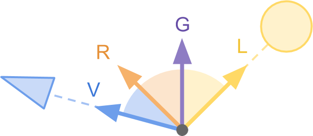
We’ll use the dot product again to measure the alignment of R and V to check if a sand grain would shimmer towards the camera. Shimmering sand is quite rare if you look at a large desert, not a lot of sand grains are actually shimmering so we’ll set a simple threshold for when a grain should shimmer.
The implementation is as follows in our GlitterSpecular method. we’ll sample the texture at first. After that use the reflect function to return the reflection vector of L and G(Nvidia developer zone, unkown). at last we’ll look how aligned the returning ray is to the camera, and if the returned value is higher than our set threshold it will return a glimmering effect to the randomly sampled texture. we’ll add this to the final colour in our custom lighting function to see the results. In figure 21 the shimmer is visible
// Random glitter direction
			// [0,1]->[-1,+1]
			//sample texture
			float2 uv = W.xz;
			float3 G = normalize(tex2D(_GlitterTex, TRANSFORM_TEX(uv, _GlitterTex)).rgb * 2 - 1);

			// Light that reflects on the glitter and hits the eye
			float3 R = reflect(L, G);
			float NdotH = max(0, dot(R, V));

			// Only the strong ones
			if (NdotH < _GlitterThreshold)
				return 0;

			// Debug glitter
			//return NdotH * fixed3(1, 1, 1);

			return NdotH * _GlitterColor;
Code snippet 8 part of the glitter function
float3 color = diffuseColor + specularColor + glitterColor;

4.5 Bump mapping
The last thing to add to the sand shader is sand ripples. Dunes are always eroded by the wind, so with this effect we’ll be adding normal maps to the terrain to recreate that effect.

With my erosion algorithm I already created some form of ripples but these aren’t very consistent and quite big. So with this bump mapping method we’ll create smaller ripples that will complement our dunes and our bigger ripples in the mesh.
To support and complement our mesh generation these maps will be added procedurally. This means that they will be added based on the geometry. In our shader this will mean that we’ll have a normal map for shallow slopes and another one for steep slopes and we’ll blend between these two in between.
The implementation is by far the most complicated one we’ve done yet. But we’ll start by using the dot product to check how aligned the normal direction of the geometry is compared to the vector that points towards the sky. If they are close to aligned it is a shallow dune, if it is not aligned and closer two 90 degrees it is a steep dune. The initial problem I encountered is that the two normals we want to use are not in the same frame of reference. The mesh normal is expressed in tangent space while the vector that points towards the sky is expressed in world space. Luckily Unity has a function called WorldNormalVector which lets us convert a vector from tangent space to world space. In order to use this function you will need to change the Input structure by adding a float3 worldNormal and INTERNAL_DATA. According to the Unity documentation INTERNAL_DATA contains world reflection vector if surface shader writes to o.normal (Unity documentation, 2017).
struct Input
		{
			float2 uv_MainTex;

			float3 worldPos;

			float3 worldNormal;
			INTERNAL_DATA
		};
Code snippet 9 adding INTERNAL_DATA to the input for world reflection.
For the implementation in the code below, In the first few lines we calculate the up direction UP_WORLD and use the N_WORLD we converted in the first line to calculate the steepness. We also have to take into account which direction the dune is facing. As a slope can be facing the X or Z direction we’ll calculate the xness, to do this we’ll again use the dot product to see how aligned the dune is to RIGHT_WORLD.
Using pow on the steepness to control how sharp the blending between the two maps is (Nvidia developer zone, unkown).
The shallow and steep normals maps called _ShallowTex and _SteepTex are sampled and blended based on steepness. We’ll use Nlerp again to combine these two again instead of slerp because it is way cheaper in terms of computing power as we discussed before.
// Converts the current surface normal from TANGENT to WORLD space
			// Compare it with UP_WORLD and RIGHT_WORLD
			float3 N_WORLD = WorldNormalVector(IN, N);

			// Calculates "steepness"
			//  0: shallow (flat surface)
			//  1: steep (90 degrees surface)
			float3 UP_WORLD = float3(0, 1, 0);
			float steepness = saturate(dot(N_WORLD, UP_WORLD));

			steepness = pow(steepness, _SteepnessSharpnessPower);
			steepness = 1 - steepness;
			//return float3(steepness, steepness, steepness);

			// Calculates "xness"
			// Slopes can be facing X or Z direction
			//  0: slope facing Z
			//  1: slope facing X
			float3 RIGHT_WORLD = float3(1, 0, 0);
			float xness = abs(dot(N_WORLD, RIGHT_WORLD)) * 2;
			//return float3(xness, xness, xness);

			// sharpen xness around 0.5
			xness = xness * 2 - 1; // [0,1]->[-1,+1]
			//return float3(xness, xness, xness);
			xness = pow(abs(xness), 1.0 / _XZBlendPower) * sign(xness); // Sharpen around 0.5
			xness = xness * 0.5 + 0.5; // [-1, +1]->[0,1]
			//return float3(xness, xness, xness);//*(1 - steepness);

			// [0,1]->[-1,+1]
			float2 uv = W.xz;
			float3 shallowX	= UnpackNormal(tex2D(_ShallowXTex,	TRANSFORM_TEX(uv, _ShallowXTex	)));
			float3 shallowZ	= UnpackNormal(tex2D(_ShallowZTex,	TRANSFORM_TEX(uv, _ShallowZTex	)));
			float3 steepX	= UnpackNormal(tex2D(_SteepXTex,	TRANSFORM_TEX(uv, _SteepXTex	)));
			float3 steepZ	= UnpackNormal(tex2D(_SteepZTex,	TRANSFORM_TEX(uv, _SteepZTex	)));

			// Wave steep
			float3 S = normalerp
			(
				normalerp(shallowZ, shallowX, xness),
				normalerp(steepZ,   steepX,   xness),
				steepness
			);

			// Rotates N towards S based on _WaveBlend
			float3 Ns = normalerp(N, S, _WaveBlend);
			return Ns;
Code snippet 10 part of the bump mapping method where the two normal maps are blending based on steepness.
In the result below you can see the normal map on the steeper part of a dune, it also blends into the other map the less steep the hill gets.

5. Post processing
In the chapter on glitter reflection we discussed that the reflection would need a light reflection that was above 100% to be able to leak into other pixels. In the intensity settings you can +1 the brightness of your HDR colour. But this alone will not let the pixels leak colours into each other.

To achieve the effect we are after and to finish the overall effect we’ll use a little bit of post-processing. I am not going to cover how to set up post-processing for your Unity projects, the documentation explains that perfectly. The most important effect from the post-processing stack we’re going to use is the Bloom effect. Applying this to your post processing volume will let the bright lights and colours in your scene leak into the objects or pixels adjacent to them. The other effect that I used is Color Grading. The game Journey has a certain set of colours used to shade almost everything in the game and with Color Grading you can really let those colours come through or adjust the color temperatures in your scene. Herman Tulleken wrote an article about the functions of colours in games and also covered Journey in the article which is where I got my inspiration from (Tulleken, H. 2015). The post processing effects and their settings are set at these values based on trial and error but originally set after the settings used by Atwood deng. (Deng, A. 2018).


The result of these post-processing effects on the scene look like this. As you can see the colours are a lot softer and the specular effects blend beautifully into the terrain.

6. Result
After 4 weeks of work I am satisfied with the procedural desert I managed to create. I think my end product is recognisable as something with the “Journey aesthetics”. In the two images below you can be the judge if I got close or not at all. Although the colour pallets I used might not be exactly right, the technique behind the shader is very close to the real thing.
// ---------------------------------
		// --- Custom Sand Lighting
		// ---------------------------------
		// W: world position
		// N: surface normal
		// L: light direction
		// V: view direction
		inline float4 LightingSand (SurfaceOutput s, fixed3 viewDir, UnityGI gi)
		{
			// Original colour
			//fixed4 pbr = LightingStandard(s, viewDir, gi);

			float3 L = gi.light.dir;
			float3 V = viewDir;
			float3 N = s.Normal;

			float3 W = worldPos;


			// all lighting calculations
			float3 diffuseColor	= TerrainDiffuse	(N, L);
			float3 rimColor		= RimLighting		(N, V);
			float3 oceanColor	= OceanSpecular		(N, L, V);
			float3 glitterColor	= GlitterSpecular	(N, L, V, W);


			//combining
			float3 specularColor = saturate(max(rimColor, oceanColor));
			float3 color = diffuseColor + specularColor + glitterColor;

			//final colour
			return float4(color * s.Albedo, 1);
		}
		// ---------------------------------
Code snippet 11 custom lighting function where all lighting models are combined to create the final colour.
All lighting function created for the shader are put together in the custom lighting function (code snippet 11) where the models are combined to construct the final colour you can see in figure 23.

I spent a little less than 2 weeks on creating the procedural terrain generation and the remaining time on recreating Journey’s sand shader. Creating the shader was easier than creating the terrain generator I wanted, mainly because my goal was too ambitious. Programming realistic aeolian erosion in a desert is a massive subject, and I didn’t realise that at the start of my research. Luckily I realised halfway through that I should readjust my scope if I wanted to finish my product on time. In the second week a teacher also told me that my scope was a little vague and maybe too broad, that was the point where I also realised that I needed to adjust it. I am glad I took the time to clean up my code and format it in such a way where it is understandable for anyone who has the slighest knowledge of the subject, even the shader is pretty well annotated for people with no shader knowledge. I got tips from Alan Zucconi himself on how to write your shader scripts more readable.
It was a very fun experience for me as Journey is one of my favourite games, and recreating something from it was very interesting. I learned a lot of new things during my research such as how to wirte surface shaders, particle simulation and another reminder that I should always be careful when setting my scope. I am satisfied with the end result and might continue improving upon the shader which I will cover in the next chapter.
7. Future work
There are a few things I wanted to try / create that I didn’t have the time for during the 4 weeks of research and development. I wanted to start with an optional part of the shader that I didn’t have time for, the moving sand ripples. This effect can be seen in the game when the main character is traversing a steep dune or gliding down slopes in the sand as seen in figure 29. These ripples would also be used to show footprints in the sand when the main character is simply walking.

A similar effect to the surfing I wanted to create is the waves of sand. In open areas in the game wind causes the sand to lift up and move just like in the video below. The effect is also supported by a particle effect that causes dust to float near the ground.
Finally, I wanted to create a different preset of the shader to replicate the snowy areas in the game. In the game Journey (without spoiling too much) you eventually venture into the snowy mountains closing in on your goal. I am not exactly sure but by looking at footage the shader used for the snow is definitely similar to the shader used for the sand, it has the granularity to it. The lighting models used might be different or not used at all but is something I should to look into if I want to recreate the snow.

Sources
Blow, J. (2004, February 26). Understanding slerp, then not using it. [Internet Resource]. http://number-none.com/product/Understanding%20Slerp,%20Then%20Not%20Using%20It/
Deng, A. (2018, Februari 22). Journey Sand. [Internet Resource]. https://github.com/AtwoodDeng/JourneySand
Edwards, John. (2013) Sand Rendering in Journey [Internet Resource]. https://youtu.be/wt2yYnBRD3U
Lague, S (2019, February 28). Coding Adventure: Hydraulic Erosion. [Internet Resource]. https://www.youtube.com/watch?v=eaXk97ujbPQ
Mcdonald, N. (2020, November 23). Simple Particle-Based Wind Erosion. [Internet Resource]. https://weigert.vsos.ethz.ch/2020/11/23/particle-based-wind-erosion/
Nvidia developer zone. (Unkown date). CG standard library. CG 3.1. [Internet Resource]. http://developer.download.nvidia.com/cg/index_stdlib.html
ThatGameCompany. (2015, July 21). Journey. [Internet Resource]. https://store.playstation.com/nl-nl/product/EP9000-CUSA00470_00-JOURNEYPS4061115?gclid=Cj0KCQjw9YWDBhDyARIsADt6sGYMSyAP3vwiAa7-YhoGSSY8jsg0usRJIS8VJc4q3TUvJmCxjdNHkgoaApeaEALw_wcB&gclsrc=aw.ds
Tulleken, H. (2015, July). Color in games: An in-depth look at one of game design’s most useful tools. [Internet Resource]. gamasutra.com/blogs/HermanTulleken/20150729/249761/Color_in_games_An_indepth_look_at_one_of_game_designs_most_useful_tools.php
Unity Documentation. (2017, June 8). Writing Surface Shaders. Unity 2020.3 [Internet Resource]. https://docs.unity3d.com/Manual/SL-SurfaceShaders.html
Williams, D. (2018, January 26). Animated voxel water with MagicaVoxel and VoxBox. [Illustration] http://www.david-williams.info/tag/procedural-generation/
Zucconi, A. (2019, October 8). A Journey Into Journey’s Sand Shader.[Internet Resource]. https://www.alanzucconi.com/2019/10/08/journey-sand-shader-2/
Zucconi, A. (2016, June 24). Physically Based Rendering and lighting models in Unity3D. [Internet Resource]. ]https://www.alanzucconi.com/2015/06/24/physically-based-rendering/


